We get it, your excited! But please take a few minutes to read the installation section of the manual before you get
started. The installation is not difficult, but there are some precautions and recommendations you need to take, particularly
with the installation of the Level Up Pro module with the Progressive Industries EMS module.
The DC wire gauge to connect the Level Up module to the trailers converter should be at least 22 gauge. The charge current for
the Level Up module is limited to 220 mA. The specified wire gauge is based on a 12 volt DC supply, a maximum of 300 mA of current,
an a two percent voltage drop margin over 20 feet of wire.
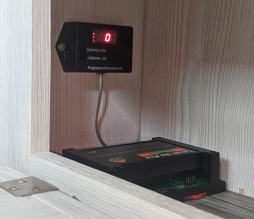
When considerating an installation position for the Level Up Pro you will need to consider the location of the Progressive Industries EMS location. The Progressive Industries EMS
module should be installed as close to the converter as possible, or if that is not an option as close to the power connector of your
RV.
Other considerations when mounting the Level Up Module:
do you have easy access to Level Up module and your Progressive Industries EMS Module.
do you have easy access to a 12 VDC source for your Level Up Pro module or
do you have easy access to a 5 VDC power source for your Level Up Pro/Lite module
have you confirmed that you can connect to your Level Up module from your tow vehicle.
keep the module as close to the front of the RV as possible.
do not install the module under metal appliances that could block bluetooth signals
ensure that the location is easy to access, dry and out of the way.
Tip
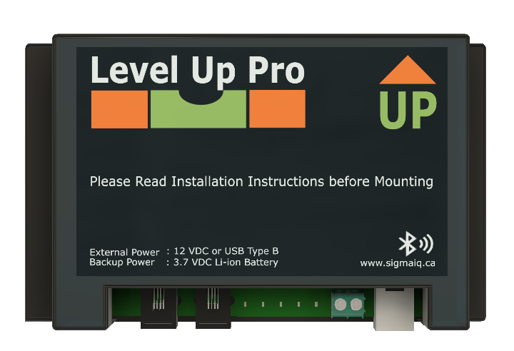
The Level Up Pro can be powered from 12 VDC or USB so consider the closest alternative.
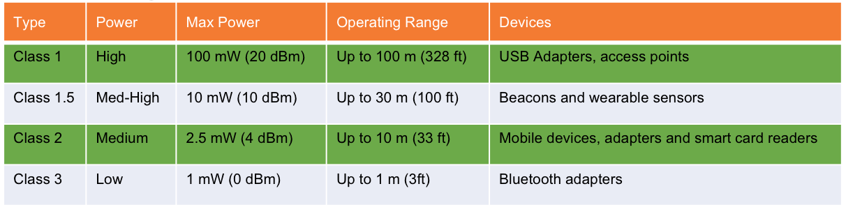
Bluetooth is a short range radio protocol. The Level Up module uses a medium to high power device. Level Up is class 1.5 radio with a maximum
theoretical range of 30 m (100ft). The chart below shows the different classes of devices.
Warning
The operating range of the Level Up module is 30m (100ft) is under ideal conditions. In real world conditions you can expect the actual
range to be considerably less.
The reliability of the connection between your mobile device (in the cab of your tow vehicle) to the Level Up module installed in your RV will vary depending on
the installation. We recommend that the Level Up module be installed as close to the front of the RV as possible. We recognize this may complicate
the wiring between the Level Up module your Progressive Industries EMS.
For more detail on how the bluetooth range could affect your installation click here for the Bluetooth Range Calculations.
The simpliest way to check that the proposed mounting location of the Level Up Pro will result in a reliable connection is to hook the RV up to
the tow vehicle and test it. Make sure the Level Up module is on and then go and sit in the cab of your truck with the windows up and the doors closed and ensure that
you can connect and maintain a connection with the Level Up module. Discconect and try an reconnect a few times to ensure that the results are consistent.
Tip
If at some point during your testing you can no longer connect to the module and previous attempts were working fine, check to
see if the Level Up Pro module is still on. Taping the module lightly with your finger should be enough to wake it back up.
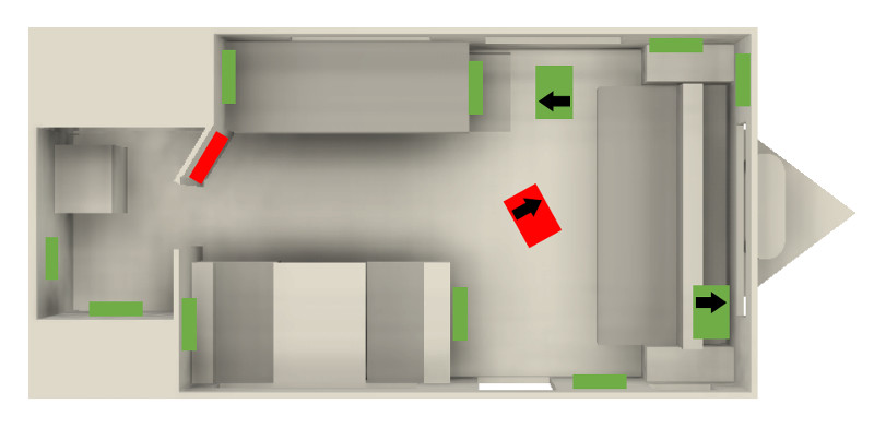
Regardless of the mounting orientation of the Level Up module it must be mounted either parallel or perpendicular to the side or the
front of the RV. Modules that are mounted on an angled wall (red boxes and red boxes with black arrow) will function with reduced accuracy,
or not function properly at all.
The Level Up module can be mounted in one of eight orientations. Four of the orientations require the
module to be mounted with connectors facing the floor, there are two floor mount options and two under deck options.
The four vertical facing options are : (note in all cases the arrow on the case must point to the ceiling)
Label Facing Rear of RV
Label Facing Front of RV
Label Facing Drivers Side of RV
Label Facing Passenger Side of RV
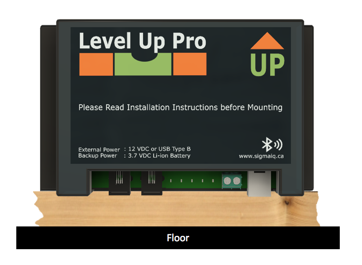
The two floor mount options are :
Label facing the ceiling and the arrow on the label facing the front of the RV
Label facing the ceiling and the arrow on the label facing the rear of the RV
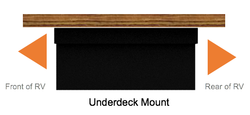
The two under deck options are :
Label facing the floor and the arrow on the label facing the front of the RV
Label facing the floor and the arrow on the label facing the rear of the RV
There are four vertical options. All require the connectors to be face down and the orange arrow pointing to the trailers
ceiling. The Level Up module label can be mounted with the arrow pointed to :
There are also two floor mounting options for the Level Up module. The module must be mounted with the label facing the
ceiling of the trailer with the orange arrow facing either the front of the trailer or the rear of the trailer.
There are also two under deck mounting options for the Level Up module. The module must be mounted with the label facing the
floor of the trailer with the orange arrow facing either the front of the trailer or the rear of the trailer.
It is important that regardless of the orientation of the mounted Level Up module that it be mounted parallel to either the
left, right, front or rear of the trailer.
Before mounting the Level Up module ensure you can see the other side of what your screwing into to ensure that you do not potentially
damage electronics, nick or cut a wiring harness, or end up with a screw sticking out into the RV or and adjacent cabinet. If there is a
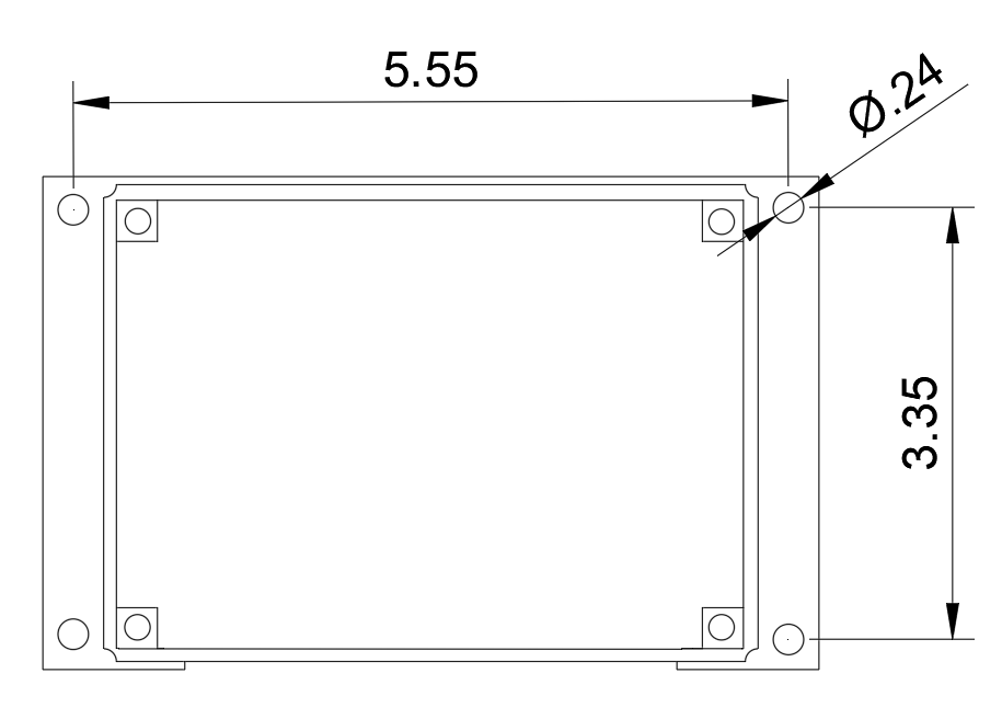
concern about the mounting material being too thin, consider using a backer board to provide more stability. The backer board only needs
to be 7” x 4.5” and a 1/8” to 1/4” inch thick ( 180 mm x 115 mm and 4 to 6 mm thick).
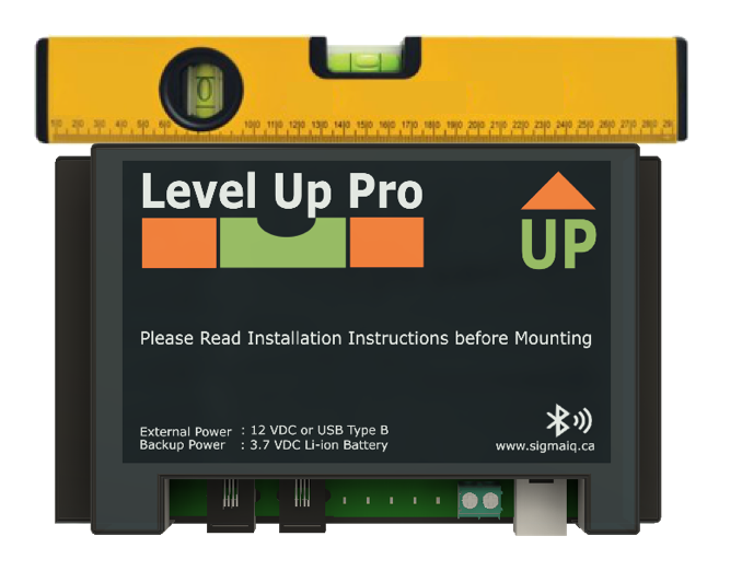
Use a spacer block to ensure that the module is parallel to the floor and or to a wall in the trailer. A piece of scrap 2 by 4 makes an ideal spacer. Mount the module with the screws provided.
When mounting the module using a level it is important to ensure that the trailer is level from
front to back and left to right, Once the trailer is level and the Level Up module is level secure
the module with the screws provided.
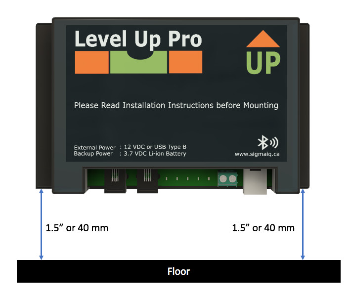
To allow for proper cable management and sufficient bend ratings on the cables please leave a minimum of
1.5” inches or 40 mm of space between the bottom of the Level Up module and the nearest obstruction.
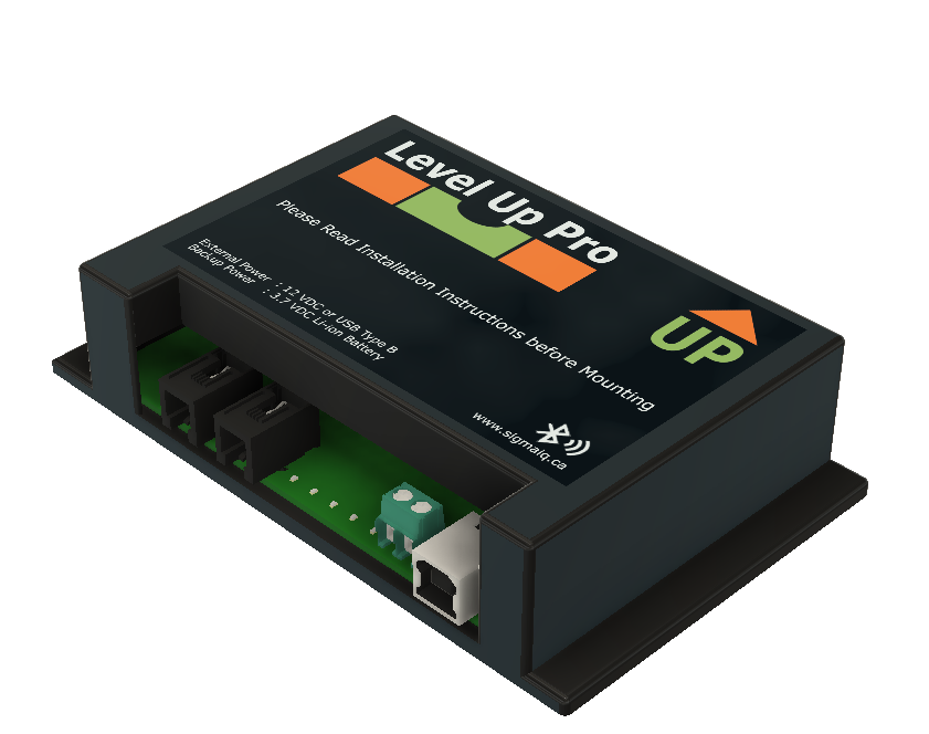
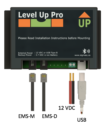
Depending on the Level Up module you purchased you will have a number of different connection to wire up. Level Up Lite
modules have a single USB power port to keep the internal battery charged, where as the Level Up Pro version has two external
power options, USB, or 12 VDC.
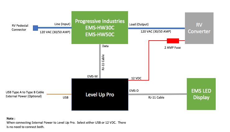
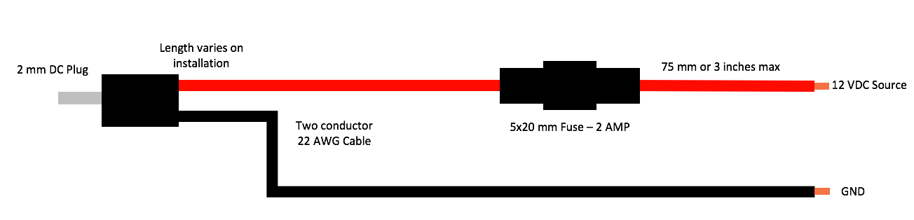
If you have decided to connect the Level Up Pro to 12 Volts either at the RV converter, directly to the battery, or at some other
convientent 12 VDC source, the fuse holder should be as close to the source as possible. As noted in the diagram, there is no need
to connect the USB and the 12 VDC external power. We would recommend connecting the Level Up module to the RV converter through
2C (two conductor) 22 gauge wire with an inline fuse.
The Level Up Pro has a built in fuse that will automatically reset. The maximum current draw for the 12 VDC charger built into
Level Up Pro is 250 mA.
Double check the wiring in your RV for the selected 12 VDC source before connecting up the Level Up Pro module. In RV and marine
installations black is 12 VDC and white is ground. Use a multimeter to confirm the polarity of the wiring. While reversing the
wiring will not affect the Level Up module as it will automatically switch polarity, it does affect the protection afforded by the
fuse. You will want to ensure that the fuse is on the 12 VDC lead not the ground wire.
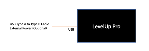
The Level Up Lite and Pro modules can also be powered/charged with a standard USB-B cable. The USB cable supplies 5 VDC to
the Level Up Lite/Pro module. The charger must be able to supply a minimum of 500mA (0.5 AMPS) or Level Up will never fully
charge. The maximum charge current of Level Up module is around 250 mA.
NEVER cut the USB-A connector off the USB cable and connect it to a 12 VDC power source. You will permanently
damage the Level Up module, the battery or both. There is a small risk of starting a fire if you connect the Level Up
module to 12 VDC through the USB connector.
Attention
Connecting the Level Up Pro through USB can simplify the installation, however it should be noted that you will loose the
ability to view the RV battery state through the Level Up application.
Once the module is mounted, you’ll need to make a number of data connections. If you have your Progressive Industries EMS
installed connect the EMS module RJ-11 to the EMS-M connection on the level Up module. Take the RJ-11 cable supplied
with Level Up and connect one end into the EMS-D connector in the Level Up module and the other end into the Progressive
Industries remote display.
Note
The EMS will work even if the EMS-M and EMS-D cables are reversed. When making the data connections ensure that the EMS
Line side is not powered. (see page 5 of the Progressive Industries Instruction Manual for more information)
Cable Name
Type
Source
EMS-M
Data
Progressive Industries EMS Module
EMS-D
Data
Progressive Industries EMD Display Module
12 VDC
Power
RV Converter, Water Pump, RV Batteries, other 12 VDC appliances
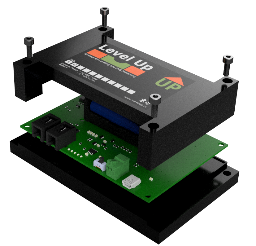
The battery is shipped installed in the module. However for Level Up modules that do not have a power switch will be shipped with a
battery isolating pull tab that must be removed before the unit will turn on. You can remove the tab without the need to remove
the battery. Simply remove the four screws from the front of the Level Up module. The pull tab is installed on the positive
terminal of the battery. Pull out the tab and replace the top cover and reinsert the four mounting screws. If you Level Up module is
equipped with a power switch, there is no need to remove the cover, simply slide the switch to the on position.
If the battery is removed for any reason,you need to ensure that the orientation of the battery is correct before snapping
it in place. The PKCELL batteries have a black patterned band around the battery indicating the negative terminal. The positive
end of the battery has a small indentation. The Negative and Positive side of the battery holder is clearly marked of the PCB.
If the battery is installed correctly the PWR indicator will light up after a couple of seconds. If you set the board down for a
while with the battery installed Level Up will go to sleep automatically and the PWR indicator will turn off.
You can now replace the cover and reinsert the four machine screws to secure the PCB into the case. The screws should be snug
but do not over torque the screws.
Important
The Level Up module cannot run without the battery installed, even if the external power (12VDC or USB) is connected. External power is for
charging the battery only, not for running the device.