Introduction
This is a multi-part series on the RF power meter I developed for insertion loss testing. While this series will get into the details this article starts with the why. In future articles, we’ll cover the hardware, schematics, battery options, Bluetooth contamination of measurements, calibration and mobile software.
The What and Why
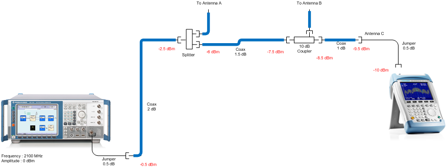
Insertion loss testing is simply inserting a known RF source level at a specific frequency into one end of the distributed antenna system and measuring the output level with an RF meter or spectrum analyzer at the other end. The difference between the injected RF level into the system and the measured level at each of the antenna locations is the insertion loss. The insertion loss testing is useful as it lets engineering know that the actual installed system, matches what the designer intended. Insertion loss testing is also helpful for technicians and installers as it provides a quick way to check that everything is connected properly.

Normally the RF engineer for the wireless carrier provides the contractor with a spreadsheet of the cable ID’s for each floor and estimated loss for each cable in the design. A column in the spreadsheet is filled in by the installer for the actual measured loss. If the measurement is outside the tolerance it could mean there is a problem with an incorrectly installed component, or a change to the design was necessary to complete the install. A typical example of a design change is when the designer assumed the cable feeding an antenna can go directly from point A to B, but in reality, the cable needed to go from points A to C and then to B. So instead of the cable being 5 meters as designed in ends up being 30 meters.
Aside from simplifying the equipment used to collect the measurements the secondary goal of this project is to automate the data measurement and collection. If you’ve been involved with any type of network installation, you know that as-built drawings are important. As-built drawings are also a pain to complete as it generally involves consolidating data collected from different individuals and equipment. If as-built drawings are not accurate or they are incomplete they aren’t worth having, and any mistake or missing data causes one to lose faith in the entire document. As the insertion loss testing is just one of many sets of results that need to be collected, it would be a huge benefit to automatically collect and catalog the results electronically.
Seriously … Another Meter

You’re probably asking yourself why on earth do you need another meter, the market is full of them, right? Well… yes and no. Most meters on the market are designed for the lab, or at best sitting on the floor in front of an open base station, in a clean well-lit space. RF power meters and portable RF power meters are either ridiculously expensive and inexpensive meters are … what’s the word I’m looking for … oh yeah junk!
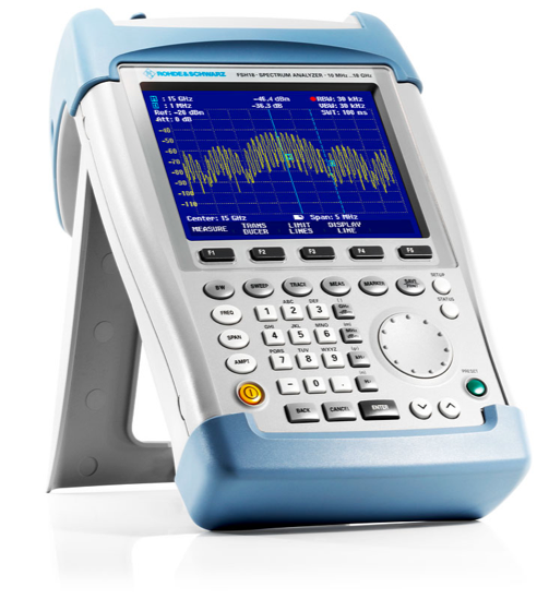
There are other options when it comes to measuring insertion loss, such as using a portable spectrum analyzer. The problem with the spectrum analyzer is that there are too many buttons and it’s too easy for technicians that don’t use these devices daily to misconfigure the device and end up with incorrect measurements.
Regardless of the solutions on the market, there was no way to automate the measurements for the field staff that wasn’t a kludge.
So, with the use case defined, the main requirements for this meter where:
a) compact and portable
b) run off AA batteries
c) robust enough to survive a drop onto a concrete floor from six feet.
d) LED work light
e) dead simple to use, no complicated setup, one button operation
f) field updatable calibration tables for each of the six bands
i) +50 Hrs Battery life.
j) Frequency range from 40 MHz to 3.8 GHz.
k) Measurement Range of +5 dBm to -75 dBm for all six of the bands.
l) Automatically record and send results
Rabbit Hole

The first rabbit hole on this project was the form factor for the meter. For me personally, settling on a case or a form factor is always the most difficult part of the project. The first prototypes of the meter looked more like a traditional handheld power meter, a connector on the top, LCD panel and some buttons on the front panel. While the early prototypes met most of the requirements it never felt to me like it was a robust solution. The screen made the device feel fragile, and while the screen was backlit it could be hard to read as the entire meter was frequently used in dark confined ceilings at awkward angles. It also had no ability to record the collected data as it had almost no storage and no way to get the data off the device even if it was stored.
So after the first prototype, I realized I wasn’t happy with it, and I wasn’t sure what I wanted, so I put the project on hold. It sat unfinished on my bench for over six months.
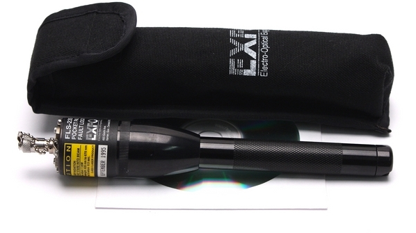
One Saturday I was cleaning up my parts closet and I happened to pick up my EXFO FLS-235 Pocket PAL. If you’re not familiar with the device, it’s used to identify faults in fibre optic cable and/or identify fibre strands. The Pocket PAL is built into a standard MAGLITE case with a custom end cap.
Form Factor

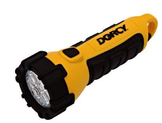
I had one of those eureka moments… why not do the same thing with the power meter. I removed the display from the design, and replaced it with Bluetooth LE module and decided to create an application for a mobile device to record and display the data from the meter. This resolved the issue of the display making the device feel fragile. It also removed all the buttons from the meter except for the power button. With the addition of the Bluetooth module clearly, the enclosure could not be aluminum. So I spent some time looking for plastic flashlights online that might be suitable. The flashlight I finally settled on was a Dorcy 41-2510 that I bought from Amazon. It looked like it would meet most of the requirements and it was also cheap… sorry I meant inexpensive.
As a flashlight, this device can pretty much be summed up as “you get what you pay for”. It was, however, perfect for this project. The goal was to use as much of the flashlight as possible. The Dorcy 41-2510 turned out to be better than I expected, and it was easy to disassemble. For the first prototype I ended up using everything except the four LED’s, a resistor and the reflective lens.
Next Up
Stay tuned for the next article when we cover the hardware design for this RF power meter.

