Introduction
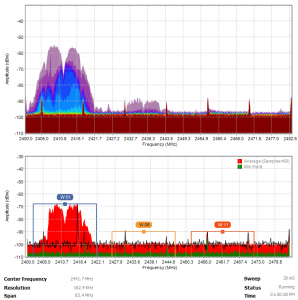
As with most of my projects this one has been on the drawing board for a while. Well over two years in fact. This project is looking to scratch a very specific itch, specifically to augment Wi-Fi measurements with noise measurements. If along the way we happen to add additional features that extend the functionality, so be it.
Wi-Fi cards provide their respective operating systems a wide range of parameters such as SSID, signal strength, frequency, bandwidth, supported network speeds, encryption type, etc. One measurement that is suspiciously absent is noise. Well actually its signal to noise (SNR), however as the name would imply if you have signal strength, you just need the noise to calculate the signal to noise ratio.
Since the signal to noise ratio (SNR) is the holy grail of signal quality I am a bit at a loss to explain why noise is/was not included in the API. I realize that this would require some amount of overhead to provide noise for the entire spectrum. I also realize that I am not the typical user and that I am approaching this from a troubleshooting/measurement standpoint. However I also know that measuring noise is possible, a number of wireless cards have implemented custom OID’s to return noise in the past, albeit limited to the associated device. I wanted a solution that would work with any number of wireless cards and across the entire 2.4 GHz ISM band… enter the spectrum analyzer. If you’re wondering why not the 5 GHz band… stay tuned.

Hardware Specifications
- Frequency Range : 2400 to 2483.5 MHz
- Resolution : 250 KHz or less
- Sweep Time : 30 mS
- Interface : USB
- Antenna : Internal
Software Specifications
- Markers : Defined Markers for Wi-Fi, BLE, Zigbee, User definable markers, Peak Markers, and a Detail Panel
- Traces : Live, Min, Max, Average, Persistence and Waterfall (future)
- Themes : Light and Dark
- Ranges : Auto Ranges, Custom Axis (frequency, channel)
Measurement Receiver

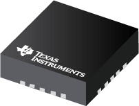
The heart of this project is the Texas Instruments CC2500. If you’ve been watching the USB spectrum analyzer space for any period of time, this should come as no surprise. This chip is a 2.4 GHz transceiver designed for low power wireless applications in the ISM B band. I am not going to go into any detail on this chip but I’ll give some highlights.
- This project only utilizes the receiver.
- The chip covers the 83.5 MHz of the 2.4 GHz Wi-Fi Band
- The chip is very flexible. Unfortunately that also means there are a lot of parameters you can tweak. (I would highly recommend downloading the SmartRF studio software from TI, even if its just to play with the parameters).
I could spend six months of Sundays going through the parameters, but the data sheet contains everything you need, and hey It’s only 96 pages long, you’ll be through it in no time.
The Prototypes
Unlike most of you, I rarely if ever get things right the first time, Heck I can barely get things right after the second, or third time go round. I do have one thing going for me however, I am persistent. I’ll begin with a brief description of all the different prototypes I went through, not because I want to document all my failures but each iteration helped to refine the requirements, improves the performance and ultimately gets me to the final hardware specifications.
Prototype 1 and 2 – Direct USB

The first two prototypes used a USB to SPI bridge. The Silicon Labs CP2130, and the second was the MCP2210 from Microchip were evaluated. What I liked about the MCP2210 was that you could apply to Microchip for your own vendor and device ID. With the USB to SPI bridge approach the role of housekeeping, calibration and data collection fell to the host device. This approach had a number of advantages.
- simple design
- no firmware required, the software running on the host had full access to the TI CC2500.
- minimize cost.
The solution also had a number of disadvantages
- it was hackable
- there was no way to offload housekeeping tasks (calibration, averaging) to the device, it had to rely on the host to get those things done.
- getting a USB vendor and device ID was expensive.
Prototype 3 – ATMega 328PU – 8-bit

This prototype along with Prototype 1 and Prototype 2 where actually being worked on in parallel. Next up was to replace the USB to SPI bridge and replace it with a micro-controller. Having a micro-controller between the host and the CC2500 has a number of advantages:
- allowed the housekeeping, calibration and averaging to be moved to the micro-controller and freed up the host computer.
- isolated the CC2500 from the host to “eliminate” hacking of the chip
The disadvantages were:
- firmware is required
- the Atmel 328PU just could not get the job done from a performance standpoint. Sweep time was just under one second, and that was with the resolution set to ~ 326KHz. Using the 328PU was useful in that it proved that this approach would work.
Prototype 4 – Atmel SAM21 32bit ARM Cortex- M0 at 48 MHz
This iteration in the design moved the micro-controller from from the 8 to 32 bits and into the realm of a ARM processor. The performance was significantly better, on the order of three to four times. The sweep time dropped to 62 mS. While still not where I wanted it to be, it was heading in the right direction. The problem with the 62 mS sweep time is that in order to get it, the hardware averaging needed to be disabled.
Prototype 5 – Freescale 32 bit ARM Cortex – M4 at 72 MHz
Next up…. Freescale/NXP Cortex M4. This micro-controller upgrade was one of pure horsepower, and it did not disappoint. The sweep time dropped to 28mS, with hardware averaging enabled.

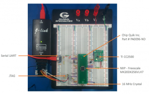
All the prototypes to date have been built on breadboard, but before we go ahead and finish up the PCB design we need to test out one additional thing on the breadboard. The previous iteration of Prototype 5 was tested with the Teensy 3.2 development board. I want to make sure that I could program the micro-controller, without the need of the Teensy boot loader. I breadboarded a stock MK20DX256VLH7 NXP/Freescale micro-controller to ensure the firmware could be uploaded using a Segger J-Link programmer. While I’m at it, I’ll will wire up the entire circuit as per my documented schematic to ensure I haven’t missed something in the design.
Bill of Materials
The approximate cost of all components need to complete this project is around $40.00 CDN. This project assumes that you have the necessary soldering equipment and soldering experience to assemble the board. The resistors and capacitors on this board are 0402 (1 mm x 0.5 mm). This project also assumes that you have a programmer, specifically the Segger J-link (aliexpress.com or equivalent) and the Tag Connect and the Tag Adapter for ARM Cortex controllers.
| QTY | Description | Manufacturer | Manufacturer Part Number |
|---|---|---|---|
| 1 | ARM® Cortex®-M4 Kinetis K20 Microcontroller IC 32-Bit 72MHz 256KB (256K x 8) FLASH 64-LQFP (10×10) | NXP | MK20DX256VLH7 |
| 1 | IC RF TxRx Only General ISM > 1GHZ 2.4GHz 20-VFQFN Exposed Pad | Texas Instruments | CC2500RGPR |
| 1 | IC REG LINEAR 3.3V 500MA 6WSON | Texas Instruments | LP38691SD-3.3/NOPB |
| 2 | 33 Ohm SMD Resistor 0402 | TE Connectivity | CPF0402B33RE1 |
| 2 | CAP CER 2.2UF 10V X5R 0402 | Murata | GRM155R61A225KE95D |
| 1 | CRYSTAL 16.0000MHZ 18PF SMD | NDX America | NX3225GB-16M-STD-CRA-2 |
| 1 | CAP CER 100PF 50V C0G/NP0 0402 | Samsung | CL05C101JB5NNNC |
| 2 | CAP CER 1PF 50V C0G/NP0 0402 | Murata Electronics North America | GJM1555C1H1R0BB01J |
| 2 | CAP CER 22PF 50V C0G/NPO 0402 | Yageo | CC0402JRNPO9BN220 |
Serial UART
The spectrum analyzer appears on the host as a serial UART. Once the host is connected to the spectrum analyzer, the host needs to send it one or more commands. Fortunately the command interface is simple, and most of the commands are optional. Commands are not case sensitive.
Command : P
Name : Product Information
Description : Returns Vendor, Product, Version, Hardware and Uptime
Required : Optional
Returns : P=Vendor=netPlan Inc.,Product=2.4 GHz Spectrum Analyzer, Version=1.0.1,Hardware=CC2500,Uptime=2675220
Command : E
Name : Execute
Description : Starts the data feed from the device to the host
Required : Mandatory
Returns : D=251311|0|[512 Bytes]
where
- 251311 = is the current uptime of the spectrum analyzer.
- 0 = is the message number – should always be zero
- [512 bytes] = is a string of 512 characters. Each character in the array corresponds to the signal strength (dBm) in bytes. RSSI are returned as positive values (for example 35 is -35 dBm). Valid values range from 20 to 110. Each byte in the array contains the signal strength value for the given resolution, beginning at the start frequency. The default Start Frequency is 2399.999268 Hz. The resolution is 162.9 KHz.
Command : Q
Name : Quit
Description : Stops the data from the device to the host
Required : Optional
Returns : Q=OK
Command : C
Name : Calibrate
Description : Executing (Command E) will automatically perform a calibration. No need to manually perform a calibration
Required : Optional
Returns : C=OK

