Bluetooth LE Measurement Contamination
I know what you’re thinking… is it a really a good idea to have a Bluetooth LE module paired with an RF power meter? Wouldn’t the integrity of the RF measurement be compromised by the Bluetooth LE module? It turns out the answer is no, well no in the sense that I could not measure any interference with my test equipment. To be perfectly honest, I really thought there would have some measurable impact on the results. In part 3, I will take you through how the measurements were collected, as well as the PCB layout techniques to mitigate contamination of the measurements.

The Setup
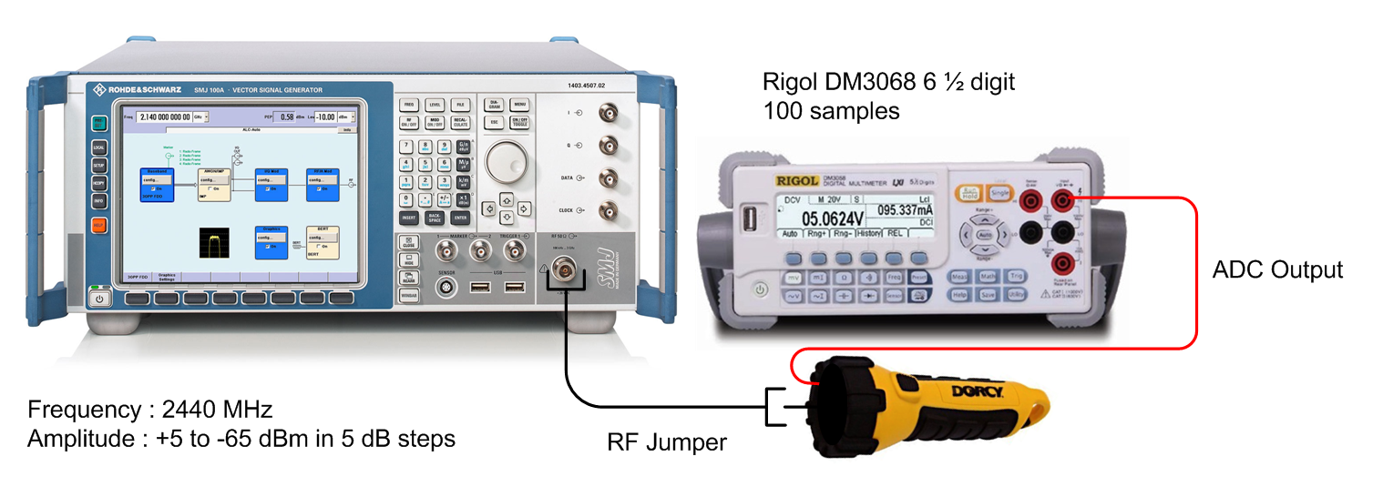
Early on in the design, the measurement contamination was something I had already been thinking about. Specifically, how was I was going to test it. A jumper was added to the PCB between the Bluetooth LE module supply and regulated supply voltage. Removing the jumper allowed the meter to be powered up while the BLE module was left in a powered down state. A test pad was added to the top side of the board. This test point allowed for DC measurements from the LT5538 module using a bench meter .
A Rhode and Schwarz SMA-100A signal generator was used to inject a 2.44 GHz CW signal from -65 to +5 dBm in 5 dB steps. The analog voltage from the meter was recorded using a Rigol DM3068 6 1/2 digit bench meter. A hundred samples on the bench meter were taken before the measurement was recorded. The measurements were repeated with the RFduino powered up. With the RFduino enabled I also tested with two different Bluetooth LE transmit levels (+4 dBm and -20 dBm).
The Results
The table below shows the side by side comparison of the result.
| RF In (dBm) | BLE Disabled | BLE +4 dBm | BLE -20 dBm |
|---|---|---|---|
| -65 | 0.357 | 0.365 | 0.364 |
| -60 | 0.381 | 0.385 | 0.385 |
| -55 | 0.433 | 0.436 | 0.435 |
| -50 | 0.518 | 0.518 | 0.517 |
| -45 | 0.612 | 0.612 | 0.611 |
| -40 | 0.699 | 0.698 | 0.697 |
| -35 | 0.790 | 0.790 | 0.789 |
| -30 | 0.884 | 0.883 | 0.882 |
| -25 | 0.978 | 0.977 | 0.976 |
| -20 | 1.069 | 1.068 | 1.067 |
| -15 | 1.159 | 1.158 | 1.157 |
| -10 | 1.251 | 1.249 | 1.248 |
| -5 | 1.354 | 1.353 | 1.351 |
| 0 | 1.449 | 1.448 | 1.446 |
| 5 | 1.529 | 1.528 | 1.527 |

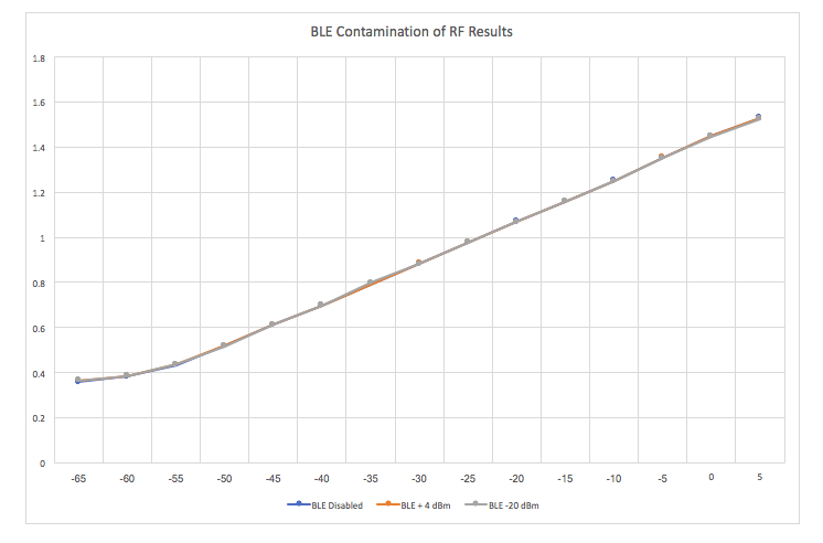
The graph to the right shows the difference in each of the three measurement sets (Disabled BLE, BLE at +4 dBm and BLE at -20 dBm). Any differences in the data sets would indicate either a problem in the test procedure or the BLE was impacting the RF measurements collected. Ideally, we are looking for a graph where all the data points from the three sets are on top of each other. The worst case difference ended up being 0.008 VDC (at -65 dBm). The average difference of 0.003 VDC. It is pretty clear from the graph below that the impact of the BLE on the measurements results are somewhere between non-existent and negligible.
The average voltage output change was 0.0166 VDC for every 1 dB change in the input. The worst case difference between all three scenarios was 0.008 VDC. When you factor in the test equipment measurement error, it’s safe to say the measurement differences are well into the weeds.
Mitigation
I had suspected from the beginning of the design process that the Bluetooth LE module would have some impact on the measurements. To maximize the isolation, the BLE module, and LT5538 RF module where placed on opposite sides of the PCB board.
The second mitigation technique was to limit the transmit power of the RFduino. The mobile application associated with the RF meter would always be within a couple of meters of the RF meter. There is no point in having the Bluetooth LE module transmitting at its maximum power of +4 dBm. To improve the isolation the transmit power of the BLE SOC was restricted to 0 dBm. The downside of the increased isolation is that it negatively impacts the range between the Meter and the mobile device.
Conclusion
With a little planning, some optimization of the settings, and a bit of testing we managed to mitigate the effects of the Bluetooth module on the RF power sensor.
Thats is it for today. Cheers.

