Hardware Description and Schematics
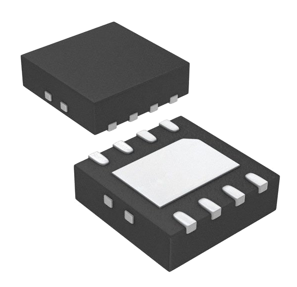
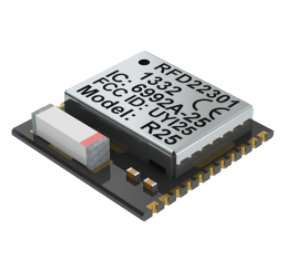
The main RF Power IC is the Linear Technologies LT5538 Power Detector and the Nordic Semiconductor nRF51822 Bluetooth SOC module.

Linear Technologies LT5538
The Nordic Semiconductor nRF51822 SOC module or more affectionately the RFduino RFD22301 is used as the microcontroller and Bluetooth LE module.
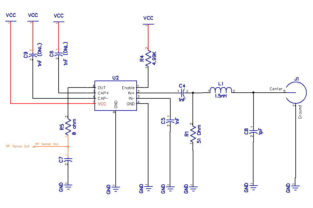
The RF power detector module is a Linear Technologies LT5538. The LT5538’s frequency range is 40 MHz to 3.8 GHz and has over 75 dB of dynamic range. The chip can measure RF signals from +10 dBm to -70 dBm across its specified frequency range. The RF section shown below is based on Linear Technologies reference design.
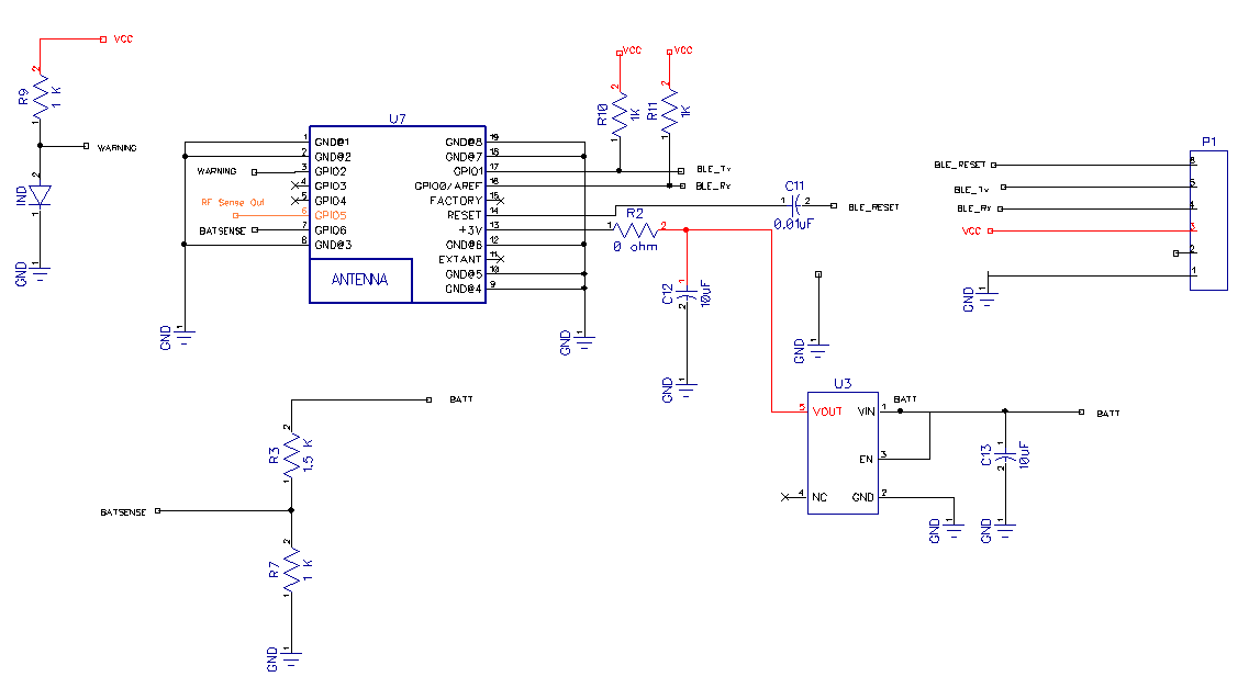
Finally, the meter also includes an Analog Device Low Quiescent CMOS Linear Regulator ADP122AUJZ-3.0-R7. The regulator was needed for the Nordic SOC. The SOC has a maximum voltage rating of 3.6 V and the raw supply voltage from the battery pack could be as high as 4.8 V. The Linear Technologies LT5538 Power Detector works with a supply voltage from 3.0 to 5.25 VDC.
RF Section
As mentioned earlier, the RF section is based on the reference design from Linear Technologies, with a few minor modifications. The power rails identified in the schematic as VCC is 3.6 VDC.
Capacitors C6, C7 and C9 are not fitted. Capacitor C7 provides some stability to the output which I found were not required. Capacitors C6 and C9 are used to set up a band-pass filter. Please refer to the datasheet for more information and for the calculation to determine their values. While values for C4, L1, C5, and C8 are from the reference design, there was a slight change with resistor R1. The 56 ohm specified in the reference design was replaced with a 51-ohm resistor.

Bluetooth SOC and Power Supply

There is really nothing special about the schematic for the SOC and power supply. The SOC is the glue that binds the LT5538 power detector to the mobile application. The P1 connector is the programming header. I did experiment with a few programming connector styles such as the standard 0.1-inch header, and the TAG-Connect TC2030 6 pin cable. While the standard 0.1-inch header was convenient it took up too much space on the PCB. In the final PCB revision, I went back to the Tag-Connect cable for programming.

While the RFD22301 was perfect, there was one slight problem after the final revision of the boards arrived. The module was retired and no longer available. More on that later.
RF Connector
I evaluated a number of connector options for the power meter. I looked at an SMA (Cinch/Johnson 142-0701-201), a BNC (TE Connectivity 5413969-2), as well as N-type and 7/16 inch DIN. The N-type connector was originally thought to be too large to fit on the PCB, the 7/16 inch DIN connector was ruled out for the same reason. The SMA connector was rejected as there was some concern about how it would stand up to abuse. Prototypes for both the SMA and the BNC connectors were built, however, in the end, I settled on the N-Type connector. The N-type connector it is larger and more robust than the SMA or BNC.
Battery Option
In the original design, I had planned on using a Lithium-ion battery with a charge circuit and a USB connector. However, once the Dorcy 41-2510 flashlight was in hand, it quickly became clear that using the AA battery carousel that came with the flashlight was the right choice. The only issue with built-in rechargeable batteries is that if you forget to charge the device at the end of a shift, you’re dead in the water the next day. Using readily available AA batteries means no waiting for the device to charge.
Design Changes
The initial battery life of the meter with AA batteries was a respectable 70 hrs, but it didn’t hit the minimum goal of 200 hrs. It turns out that with a few additional lines of code and a single change to the PCB design, the battery life jumped to around 500 hrs. With the design changes, the average current draw dropped from 36 mA to 5 mA. Initially, I thought that the trade-off for increasing the battery life would result in measurement issues due to the settling time of the power sensor. According to the Linear Technologies specification sheet, the setting time is around 300nS. The design change did not appear to have a negative impact on the measurement results.
Coming Up Next
That ends the overview of the hardware portion of the RF Power Meter. If you missed the introduction, click here. On the next installment, we’ll talk about the insanity of a Bluetooth LE module in an RF power meter (let that sink in).
That’s it for this one. Cheers.

