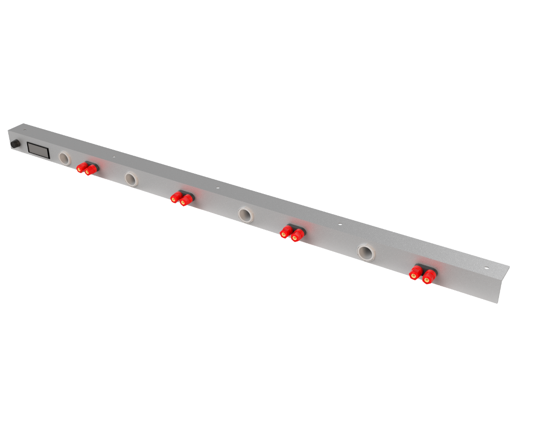
While I love my Rigol DP832, there are times when the project I have on the bench outstrips the Rigol’s ability to deliver the required current. Enter a simple linear power supply and a custom bench mounted power strip.
I have had a couple of 13.8 VDC linear power supplies from Sinclabs sitting around the lab for a while now (17 years in fact… yeah I’m not kidding). The power supply I am referring to is the SP12-B, which I have long since removed the attached battery pack, so I guess it should be more accurately designated the SP12. These power supplies were/are popular with the HAM radio crowd as well as with commercial VHF and UHF 2-way radio systems. The SP12 can deliver 7 AMPS continuous and 11 AMPS for 60 seconds with a 90-second idle time.
My requirements for this project were modest.
- I wanted a thirty-six-inch long aluminum strip mounted on the underside of the top shelf of my bench.
- I wanted a digital meter to display both the voltage and the current for all the devices plugged into the strip.
- I also wanted four pairs of banana plugs,
- two cigarette lighter adapters, and
- two dual-port USB connectors for charging.
- Panel Mount 10 AMP fuse and holder
Bill of Materials
Some of the parts were purchased on Amazon, so long-term availability would be an issue. Since this is a one-off project, I don’t mind sourcing parts that may not be available next week let alone next year. If you’re looking for these parts your mileage may vary. The cigarette lighter adapter and USB charger (SODIAL(R) Dual Car Cigarette Lighter Socket) part took over three months to arrive, so I would recommend another source.
| Description | Vendor | Part Number | QTY | Cost | Extended |
|---|---|---|---|---|---|
| Aluminum Corner 1/8″ x 1 1/2″ x 4′ | Hillman Group | 11451 | 1 | ||
| SODIAL(R) Dual Car Cigarette Lighter Socket Splitter 12V Charger USB Power Adapter | Amazon | 022735 | 2 | 8.44 | 16.88 |
| DROK® Voltmeter Ammeter Volt Amp Multimeter DC 4.5-30V | Amazon | 100177 | 1 | 20.70 | 20.70 |
| uxcell® Speaker Amplifier Dual Binding Post Banana Plug Socket Connectors (set of 5) | Amazon | LYSB012T3O71I-ELECTRNCS | 1 | 11.33 | 11.33 |
Supplies
- Painters Tape
- 10 Gauge Wire (red and black) approximately 4 ft of each
- Shrink Wrap
- Spade Bits (qty 8)
- 1/2 inch mounting Screws (Qty 5)
- Conical Anchors for 1/4 inch screws (used as spacers to keep the positive terminals from shorting out on the aluminum strip).
- Sand Paper (400 grit and 500 grit wet/dry)
Tools
- Soldering Iron
- Multimeter
- Jigsaw
- File set
- Drill
- Heat Gun
- Side Cutters, Wire Cutters
- Measuring Tape
- Sharpie (Is a Sharpie a tool ?)
- Small wrench set
- Step Bit (1 1/8 inch)
- 1/16 inch bit (pilot holes)
- Jigsaw blade for soft metal
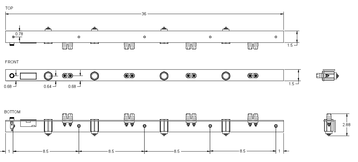
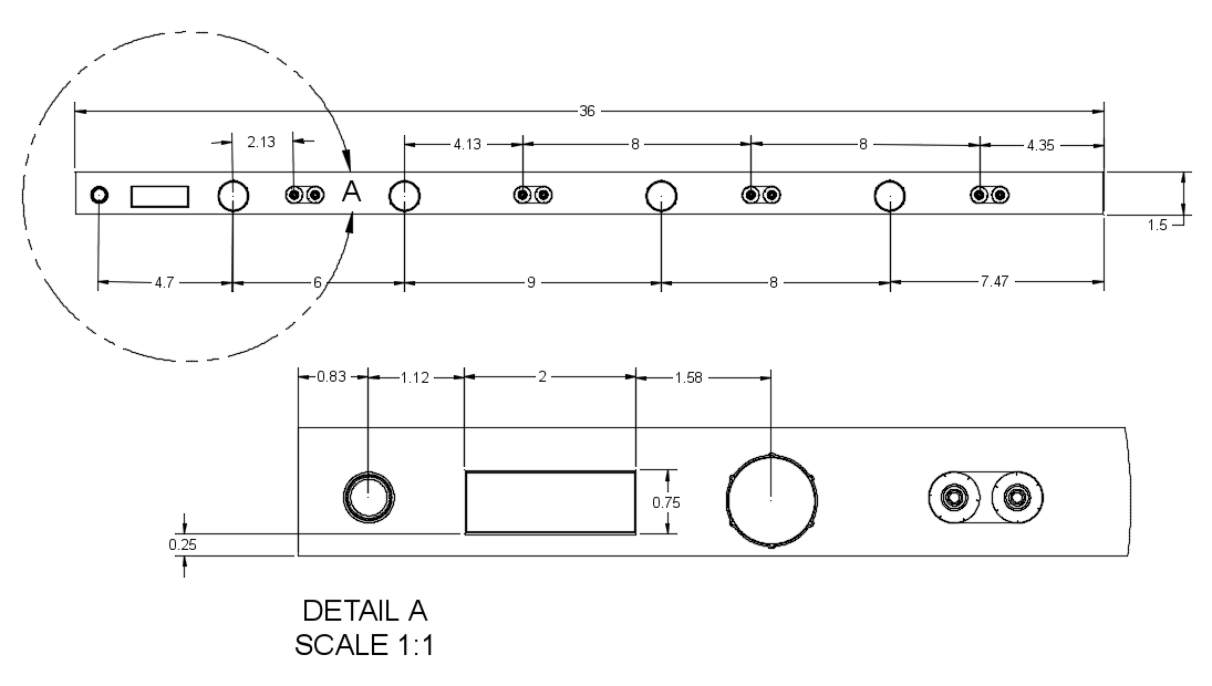
Drawing (top, front, bottom, and side)
I have been spending some time learning Fusion 360, so I thought it would be cool to draw up the project and render it in 3D. I was a little surprised at just how realistic the model was once the power strip was assembled. Aside from the cutouts, the layout dimensions are not critical. The Fusion 360 model provided a rough layout so that I had a place to start, and this would ensure that the parts would fit and not interfere with the top edge.

I would highly recommend taping off the front and top of the aluminum with painters tape to both protect the surface and provide a surface to mark out your proposed layout. With the cutouts and the drilling you are going to end up with a lot of aluminum debris, that could easily end up scratching the front face of the aluminum bar. The painter’s tape did a great job protecting the face, but after all the cutting, drilling and filing, I went over the front face with 400 grit sandpaper and then went over it again with 500 grit wet/dry paper.

Circuit Diagram
The circuit diagram for this project is very simple, all the ports are wired across the power rails through a 10 AMP fuse. The current shunt is in line with the ground rail (very important), and the meter is wired up as per the vendor’s instructions. There is a second power feed (not shown) for the meter which is used to power the electronics in the meter.

Isolating the Screw Terminals
The first issue with the dual binding posts was how do I isolate the positive post from the aluminum strip. My first thought was to use heat shrink, but I was concerned with wear and that it would eventually short out the terminal. After a bit of searching, I found shoulder bushings on Digikey (RP368-ND). I was all set to order them when I found some plastic anchors that I had on hand and they fit the holes I had already drilled perfectly. I then test fit the anchors in the holes and then cut the back of the anchor with side cutters so that they would be flush with the back of the aluminum strip. I checked each pair of terminals using a multimeter to ensure that the posts were completely isolated. I was originally only going to use the anchor on the positive pole, but the backing plate on the terminals fit better when the anchors were used on both the positive and negative terminals.

The anchors can be picked them up at any hardware store. The anchors I have are from Paulin, 843-430. These anchors are for No 10-12 x 1-inch screws. If there is one issue using the anchors it is that the shoulder is a little thicker than I would have liked. To be fair though I’m not sure the RP368-ND would have been any better.
Pre-Installation Testing
I thought it might be a good idea to test everything before mounting it on the bench, so I hooked up my 17-year-old Sinclabs SP12 power supply to the power strip and tested the ports (cigarette lighter adapters, banana plugs and the USB connectors). The DC voltage on the panel meter read a little high, but the meter has a few trim pots to tweak the voltage and the current (I would recommend trimming those pots before mounting the strip).

So Much for Being Done
One thing I was not crazy about is that the current shunt is so big that it could not be mounted on the aluminum strip. The only option was to mount it under the shelf behind the power strip. I would have been OK with this as a solution, but I decided to head back to Amazon and look for another panel meter. Enter the DROK Digital Display DC Voltmeter Ammeter 0-100 VDC 0-15 AMP. This panel meter has more functionality, more resolution, a built-in current shunt and fits in the same cutout as the original panel meter. The new meter is rated at a maximum of 15 AMPs but that’s not an issue as I have a 10 AMP fuse in the fuse holder.
Outcome
This is a project that anyone can do. The biggest challenge was cutting the hole for the panel meter. It wasn’t difficult, just time-consuming (OK… it was extremely tedious). I ended up spending a lot of time filing and testing fitting. I wanted the meter to fit tightly in the cutout and so I specifically cut the hole on the small size and snuck up on the outline using a file. I highly recommend using the painter’s tape on the front face to protect it from all the drilling and filing. I would also recommend you dry and wet sand once all the holes are cut. The sanding provides a really nice brushed look.
I think that’s it. Cheers!

